
Many modern wireless products do not use FEC. FEC is an error control technique developed by the aerospace industry for deep space exploration that can locate and correct transmission errors. Early error control schemes used error detection, as opposed to error correction. In error detection an isolated error is detected in a block of data, and the data is discarded and a request for re-transmission is made to the source. CRC (Cyclic Redundancy Check), parity, and ARQ are examples of error detection / retransmission schemes. These methods consume bandwidth during re-transmission, which adds significant latency (delay). Error correction techniques, on the other hand, add enough data encoding to allow the detection and correction of errors on the fly, and do not add significant latency, degrading traffic throughput. With powerful Forward Error Correction packets do not need to be retransmitted. Forward error correction requires significant processing power to support high data rates. The FEC encode/decode in the Wavespan 5800 is implemented in a CMOS integrated circuit.
Forward error correction is generally separated into convolutional coding and block coding. Convolutional coding tends to consume bandwidth heavily; for example, a rate ? convolutional coder/decoder requires twice the bandwidth of an uncoded system. This bandwidth inefficiency generally restricts convolutional coding to satellite links where bandwidth is more available than terrestrial links.
Block coding, particularly Reed-Solomon coding, is a very powerful tool for error control, and is very bandwidth-efficient. The powerful t=8 Reed Solomon block code used in the Wavespan 5800 consumes only 14% extra bandwidth, but it can convert a hypothetical 1x10⁻⁴ BER over the link into 1x10-17 BER delivered to the customer - the equivalent of one bit error every 317 years at 10 Mb/s! Because the 5800 is designed to operate with a worst-case faded BER of 10-6, the delivered BER is very close to perfect 24-hours a day in any weather conditions.
This may seem like magic. How is this possible for such a small amount of overhead? The answer is that the small amount of redundancy added in the transmitter is used by the signal processing system in the receiver to correct errors and deliver a reliable signal to the customer.
![]()
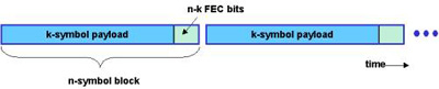
(n,k) Block Code
Here's an example to help understand how block coding works. In the transmitter, the traffic is grouped into blocks, and a small amount of extra information is added to each block. The blocks are sent to the receiver, and the receiver uses all the bits in the block - the 'k' information bits and the 'n-k' FEC bits - to locate and correct errors in the transmission. The extra bits are removed prior to the payload being delivered to the customer.
The power of the block code is called the 't' value, with higher numbers being better. Most wireless products have either no FEC at all, or at most have t=1 to t=5. The 5800 uses a (128,112) t=8 code, meaning it can correct any 8 bytes of data per 128-byte block that have errors in them.
Here's an example of a simple (7,4) t=1 code. (This would never be used in an actual product, with its 75% overhead and low correction ability, but it is useful to visualize how a block code works.) Data is organized into 7-bit blocks in the transmitter,
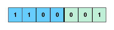
consisting of 4 bits of payload and 3 FEC bits per block. An example is shown for a traffic data pattern of 1, 1, 0, 0. The FEC bits are calculated in the transmitter to be 0, 0, 1 using a combinational logic circuit (not shown), and all bits are sent over the link.
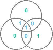
The payload and FEC bits are analyzed in the receiver, and any single bit error in the block of 7 bits (remember this example is only a t=1 code) is located and corrected as explained below. Refer to the diagram, in which the payload bits are shown in blue numerals and the FEC bits are shown in green numerals.
The receiver checks the parity of each of the circles (4 bits per circle). In this example, even parity is used (i.e. the XOR sum of the 4 bits in each circle should be 0). If the parity of all three circles is wrong, the "center" bit (a 1 in this case) is in error, and it is corrected. If the parity of two circles is wrong, the payload bit in common with the two circles, but not in common with the circle with correct parity, is in error, and it is corrected. If only one circle has wrong parity, that means one of the FEC bits is in error, and all the payload bits are correct, so the receiver delivers the correct payload to the customer. If the parity of all three circles is correct, there are no errors in the block. In this way, FEC can locate and correct transmission errors before they are passed on to the customer. The actual operation of a t=8 FEC is a bit more complex than this example, but it's helpful to visualize how forward error correction works.
1 Reed-Solomon
codes are also used in deep space probes, computer memories, and CD/CD-ROM drives.![]()